The Build - Page 3
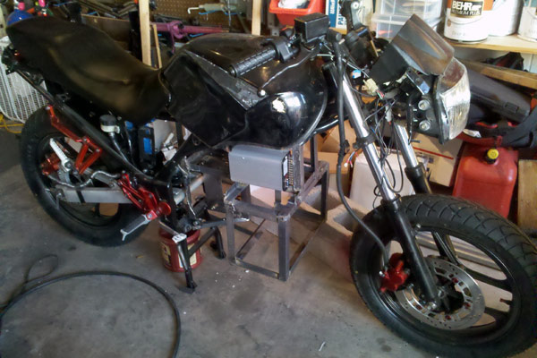
This was the first test-fitting of the brackets after assembly. Some of the electronics, like the throttle and dash are already in place, and I'd cut the rotted chunks out of the seat foam, replaced them with fresh sculpted (thanks to a $3 electric carving knife from eBay) foam and recovered it. It was hard at this point to focus on the remaining work to be done, instead of just sitting on the bike making "Vroom! Vroom!" noises.
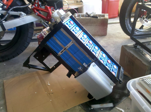
Here's the upper bracket, assembled with components attached. The white cylinder in the back is the main contactor relay, which makes or breaks the main power connection between the motor, battery pack and motor controller. The control electronics in the motor controller are actually powered by a separate circuit. Turning off the main contactor with the kill switch is a safety mechanism in case of controller failure causing unintended accelleration, Toyota style. Next step after this is attaching the BMS boards and busbars to wire all those batteries together.
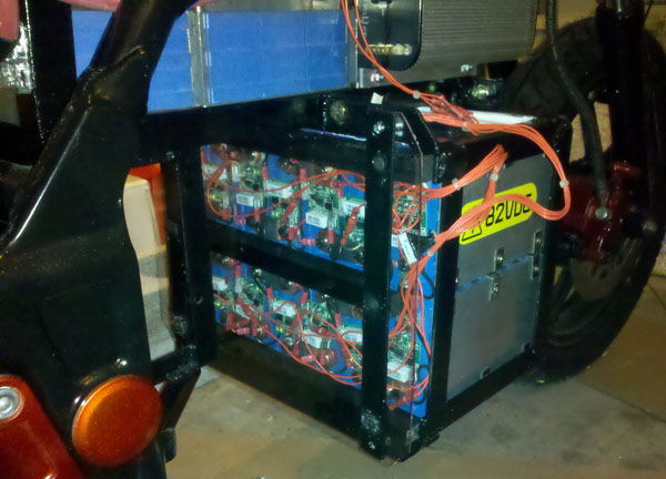
Here's the lower bracket loaded and in place. The acrylic cover provides splash and small debris protection. It is held in place by a pair of steel strips, which also hold down three wood strips that ensure that the batteries are locked snugly in place. Similar side rails prevent the batteries in the upper mount from bouncing up and around. The bundles of red wires hanging out the side, are the Cell-Log8 test leads, and are now routed so that they aren't on the outside of the bike, and have additional wire loom protecting them.
Although this design leaves the battery faces well shielded, it also makes them difficult to access. The motor must be removed (which also requires removal of the chain - still *way* easier than pulling an internal combustion engine) in order to provide clearance for the battery cover.
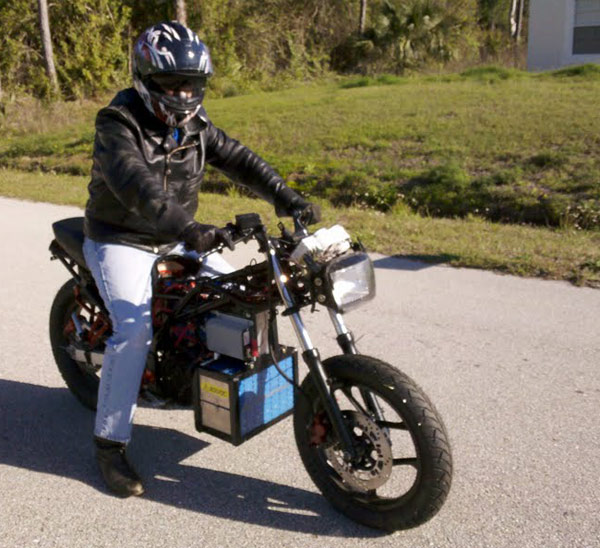
The Frankenride - "It's alive!"